simple block (no block controls)
Let's start with something very simple: the block instrument in its most basic form without any controls added. This is sometimes called 'free block'. Here's a wiring diagram for an LNER single needle block instrument:
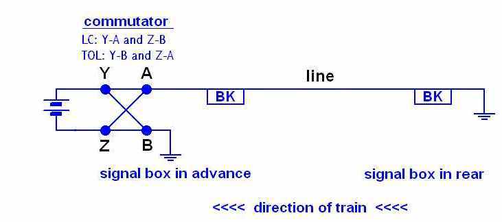 The commutator has three positions: Line Clear (LC), Line Blocked (LB),
and Train on Line (TOL). The electrical connections are made as indicated. No connections
are made at Line Blocked. Note that at Line Clear, positive is connected to line; this
was usually - but not always! - the case on the LNER.
The 'box' marked BK is the block indicator needle, through which the current flows on its way
to the block line and the signal box in rear. The block indicators at both signal boxes are
wired in series.
The previous diagram shows the block instrument powered from a battery. It is also possible to connect
it to centre tapped supply, as shown here:
The commutator has three positions: Line Clear (LC), Line Blocked (LB),
and Train on Line (TOL). The electrical connections are made as indicated. No connections
are made at Line Blocked. Note that at Line Clear, positive is connected to line; this
was usually - but not always! - the case on the LNER.
The 'box' marked BK is the block indicator needle, through which the current flows on its way
to the block line and the signal box in rear. The block indicators at both signal boxes are
wired in series.
The previous diagram shows the block instrument powered from a battery. It is also possible to connect
it to centre tapped supply, as shown here:
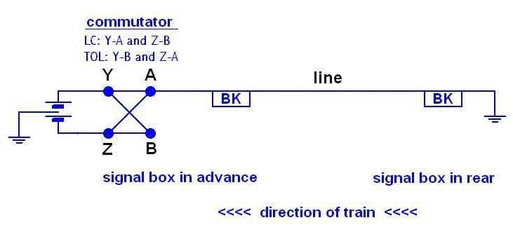 In this case there is no connection to terminal B.
Although these notes are concerned with LNER instruments, the simple forms of
MR, LNWR and CLC instruments were pretty much the same, except perhaps for the labelling of the
terminals. Also, the LMS tended to have negative line clear, in contrast to the LNER!
Example 1
Here's an actual example:
In this case there is no connection to terminal B.
Although these notes are concerned with LNER instruments, the simple forms of
MR, LNWR and CLC instruments were pretty much the same, except perhaps for the labelling of the
terminals. Also, the LMS tended to have negative line clear, in contrast to the LNER!
Example 1
Here's an actual example:
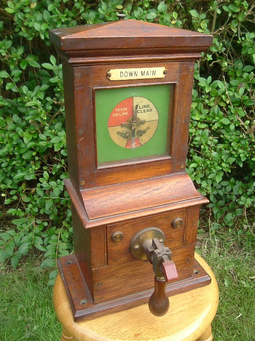 This example is an ex-GCR instrument - note the letters 'GCR' on the dial, and the characteristic 'thumb-
catch' on the commutator handle. It seems to be in more-or-less as built condition, save
for the addition of pegs to limit the movement of the needle, which, unfortunately,
obscure the GCR lettring on the dial. The line blocked segment of the dial is usually coloured
green, but this specimen seems to have faded to white over the years.
Opening it up, we find its only connections to the outside world are three yellow wires, with
no
connection to terminal B. Hence it was used with a centre tapped supply and not a battery.
This example is an ex-GCR instrument - note the letters 'GCR' on the dial, and the characteristic 'thumb-
catch' on the commutator handle. It seems to be in more-or-less as built condition, save
for the addition of pegs to limit the movement of the needle, which, unfortunately,
obscure the GCR lettring on the dial. The line blocked segment of the dial is usually coloured
green, but this specimen seems to have faded to white over the years.
Opening it up, we find its only connections to the outside world are three yellow wires, with
no
connection to terminal B. Hence it was used with a centre tapped supply and not a battery.
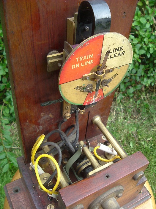 The wires retain their tubular labels, and the block line is labelled 'MH DOWN BLOCK'. Some
detective work, along with other evidence, suggests it is very probably from
Tinsley West, working to Meadowhall (near Sheffield).
'Drop handle' blocks similar to this were very common on the LNER, especially in former
GCR, GNR, and NBR territory. But there were other varieties, too:
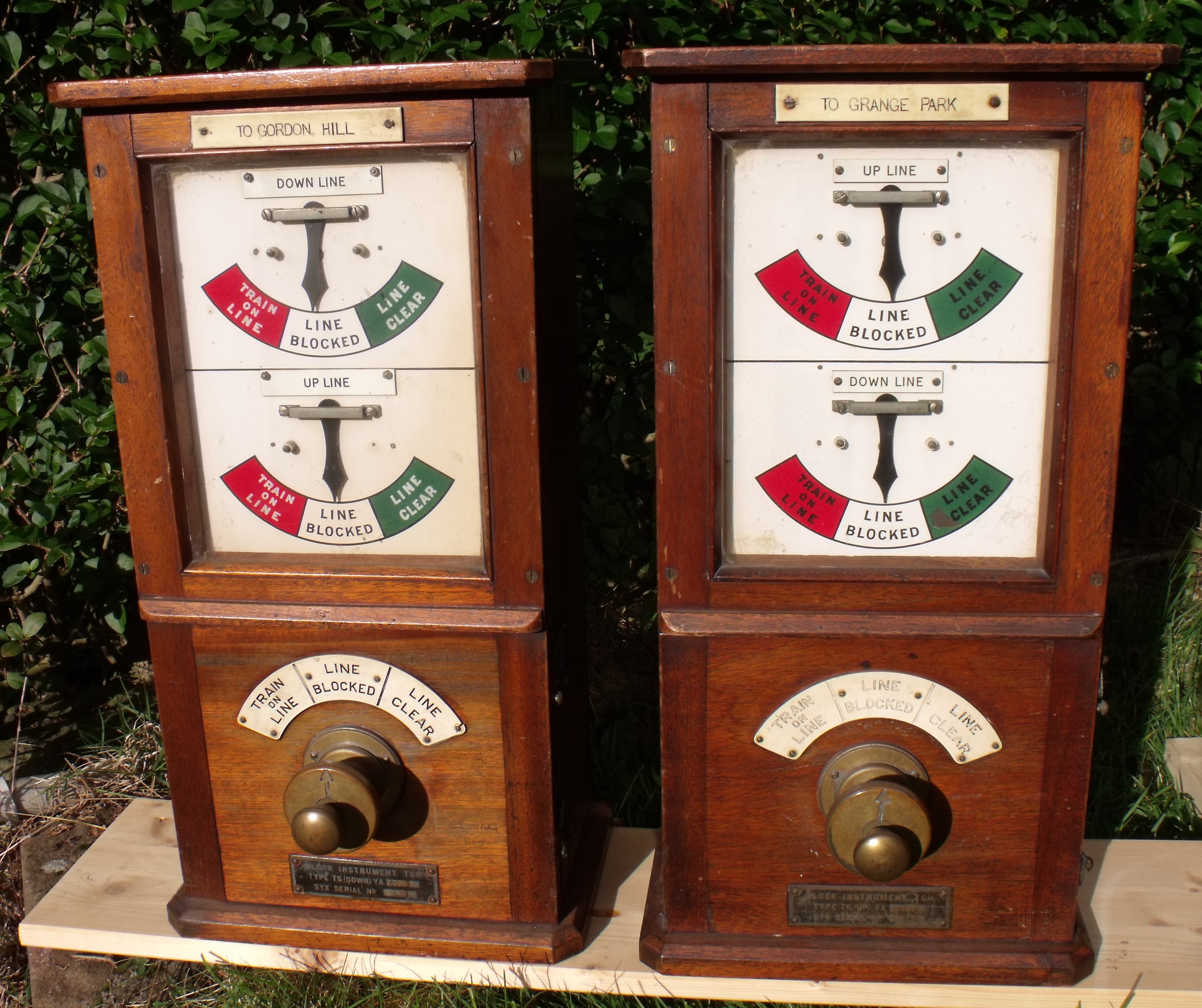
Example 2 - Sykes 3 wire, 3 position block
With time, it was found convenient to incorporate block instruments for both lines
(i.e. both pegger and non-pegger), and often also the bell, into a single unit, as this saved
space on the block shelf. Various types of such combined block instruments were eventually
to be found on the LNER.
The magnificent instruments shown below came from
Enfield Chase on the ex-GNR Enfield Loop. Click on
image for a larger view.
The wires retain their tubular labels, and the block line is labelled 'MH DOWN BLOCK'. Some
detective work, along with other evidence, suggests it is very probably from
Tinsley West, working to Meadowhall (near Sheffield).
'Drop handle' blocks similar to this were very common on the LNER, especially in former
GCR, GNR, and NBR territory. But there were other varieties, too:
Example 2 - Sykes 3 wire, 3 position block
With time, it was found convenient to incorporate block instruments for both lines
(i.e. both pegger and non-pegger), and often also the bell, into a single unit, as this saved
space on the block shelf. Various types of such combined block instruments were eventually
to be found on the LNER.
The magnificent instruments shown below came from
Enfield Chase on the ex-GNR Enfield Loop. Click on
image for a larger view.
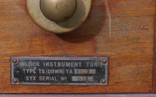
 Instruments of this particular type were built by Sykes & Co (they marked their instruments 'SYX')
for the
War Department during World War II, and were used to re-equip war devastated railways on the
continent when they were rehabilitated by allied railway troops. When continental operating
practices were resumed, the instruments became surplus to requirements. Some were acquired
by the LNER and
found their way onto the English railway network.
The bell itself is contained
within the instrument, and is operated by a plunger in the centre of the commutator.
Hiding the bell within the instrument has the disadvantage you cannot flick it to remind yourself
of the tone. Someone seems to have had just this problem at Enfield Chase, as they have written
'CLANG LOW' on the instrument! The other, which has a smaller, higher pitched, bell, is marked
'RING SOFT'.
Instruments of this particular type were built by Sykes & Co (they marked their instruments 'SYX')
for the
War Department during World War II, and were used to re-equip war devastated railways on the
continent when they were rehabilitated by allied railway troops. When continental operating
practices were resumed, the instruments became surplus to requirements. Some were acquired
by the LNER and
found their way onto the English railway network.
The bell itself is contained
within the instrument, and is operated by a plunger in the centre of the commutator.
Hiding the bell within the instrument has the disadvantage you cannot flick it to remind yourself
of the tone. Someone seems to have had just this problem at Enfield Chase, as they have written
'CLANG LOW' on the instrument! The other, which has a smaller, higher pitched, bell, is marked
'RING SOFT'.
 The same type of block instruments were in use elsewhere on the Enfield Loop at Grange
Park and Crews Hill. Although my instruments have a bell plunger, examples also existed with a bell tapper. Two
of these are visible in photographs of the block shelf at Wakefield Westgate South.
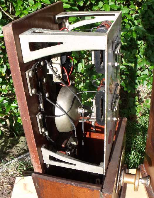
Here is a view showing the bell inside the instrument:
The same type of block instruments were in use elsewhere on the Enfield Loop at Grange
Park and Crews Hill. Although my instruments have a bell plunger, examples also existed with a bell tapper. Two
of these are visible in photographs of the block shelf at Wakefield Westgate South.
Here is a view showing the bell inside the instrument:
 Despite their size, these instruments are still simple block, with no controls. They do,
however, come with a wiring diagram attached to the inside of the case, for easy installation!
Click on image for larger view.
Despite their size, these instruments are still simple block, with no controls. They do,
however, come with a wiring diagram attached to the inside of the case, for easy installation!
Click on image for larger view.
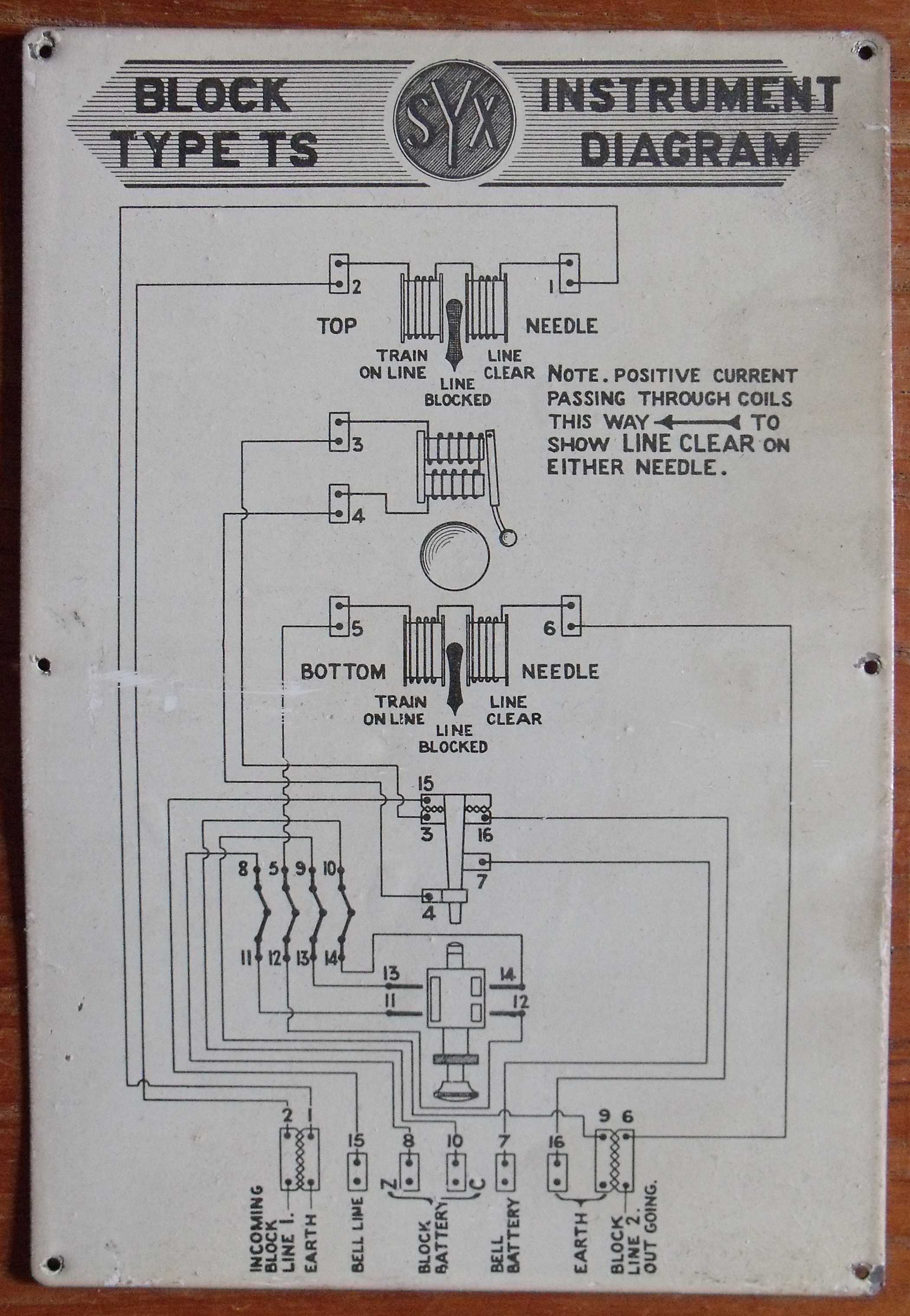 Since the commutator is connected directly to the needle, it is easy to determine that these
instruments were negative line clear, which was not the LNER standard.
Background information about these Sykes Instruments was gleaned from the following sources:
(1) an article by John Young about LNER signalling insruments
in an issue of the Railway Collectors Journal, (2) an article
by Peter Kay on the Enfield Loop, in British Railways Illustrated, volume 8, p228 (March 1999), which
includes interior photographs of most of the boxes and (3) an interior photograph of
Westgate South by A M Ross, in The Great Northern Railway in the West Riding, by
Martin Bairstow.
Since the commutator is connected directly to the needle, it is easy to determine that these
instruments were negative line clear, which was not the LNER standard.
Background information about these Sykes Instruments was gleaned from the following sources:
(1) an article by John Young about LNER signalling insruments
in an issue of the Railway Collectors Journal, (2) an article
by Peter Kay on the Enfield Loop, in British Railways Illustrated, volume 8, p228 (March 1999), which
includes interior photographs of most of the boxes and (3) an interior photograph of
Westgate South by A M Ross, in The Great Northern Railway in the West Riding, by
Martin Bairstow.