circuit 1B examples
Circuit 1B appears to be more common than circuit 1A. Circuit 1B is found:
in most modified single needle drop handle instruments (various controls) built into some Thompson instruments (full block controls) I have also found one example in a modified Tyer permissive block (signal proving only) Example 1 (proving circuit and track circuit control only): The most common place to find circuit 1B is in the single needle drop handle blocks, which have been modified by the addition of a full height back box. This example is an ex-GNR instrument (note the 'pistol-grip' catch on the commutator handle), which came from the Hexthorpe area. Look inside and we see that the commutator shaft has been extended:
 Remove the back box cover and we find one relay, two sets of contacts arranged
to open with the commutator at Line Clear, and neat set of labelled screw terminals.
The relay is the BCS relay, and the contacts are C1 and C2 on my diagrams.
Remove the back box cover and we find one relay, two sets of contacts arranged
to open with the commutator at Line Clear, and neat set of labelled screw terminals.
The relay is the BCS relay, and the contacts are C1 and C2 on my diagrams.
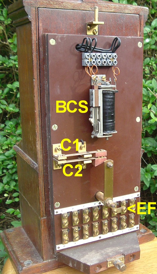 Note the neat link between terminals E and F. This demonstrates
this particular instrument was not in fact used
with track circuit control of the needle, even though it is fitted with contacts C2
and terminals H-J.
With track circuit control of the needle, a relay
is inserted between E and F, which allows the equipment to override the indication selected
by the commutator.
Example 2 (full block controls)
Here's an example of a drop handle block, modified for full block controls. Removing the
back box cover, we find two relays, a small rectifier, and both contacts C1 and C2:
Note the neat link between terminals E and F. This demonstrates
this particular instrument was not in fact used
with track circuit control of the needle, even though it is fitted with contacts C2
and terminals H-J.
With track circuit control of the needle, a relay
is inserted between E and F, which allows the equipment to override the indication selected
by the commutator.
Example 2 (full block controls)
Here's an example of a drop handle block, modified for full block controls. Removing the
back box cover, we find two relays, a small rectifier, and both contacts C1 and C2:
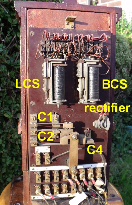 Note also that the E-F link has been removed, allowing track circuit control of the needle.
Example 3 (full block controls)
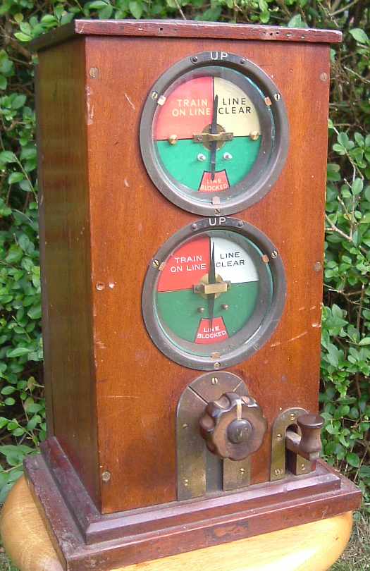
Here's another Thompson block. Look carefully at the surrounds to the dials, and you
will see that - unusually - both are labelled UP LINE - the reason for this will be explained later.
Note also that the E-F link has been removed, allowing track circuit control of the needle.
Example 3 (full block controls)
Here's another Thompson block. Look carefully at the surrounds to the dials, and you
will see that - unusually - both are labelled UP LINE - the reason for this will be explained later.
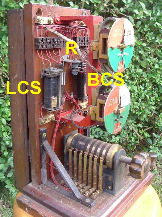
 Looking inside, we see the LCS and BCS relays, but instead of the ratchet contact arrangement,
we find a small rectifier (labelled R).
Looking inside, we see the LCS and BCS relays, but instead of the ratchet contact arrangement,
we find a small rectifier (labelled R).
 We also note the conncection to the needle units have been stretched and reversed - indicating
use with 'negative line clear'. We can be pretty sure this was done by the railway, as
this block was locked when I bought it, and I had to saw off two padlocks to get into it!
I mentioned both indicators are labelled UP LINE. This is unusual; usually a double
needle block is configured
so that the whole instrument works to one adjacent signal box, and one needle is for the
up line and the other for the down. All becomes clear when we remove the back cover:
We also note the conncection to the needle units have been stretched and reversed - indicating
use with 'negative line clear'. We can be pretty sure this was done by the railway, as
this block was locked when I bought it, and I had to saw off two padlocks to get into it!
I mentioned both indicators are labelled UP LINE. This is unusual; usually a double
needle block is configured
so that the whole instrument works to one adjacent signal box, and one needle is for the
up line and the other for the down. All becomes clear when we remove the back cover:
 We find a full set of wiring labels, which reveal the origin of this instrument. The pegging
part of the instrument worked to 'WN' and the non pegging part to 'HAT2'. Hence we can be sure
the instrument is from Welwyn Garden City signal box - rather appropriate for an instrument
fitted with Welwyn Control!
At the southern end of its main line, the GNR tended to have some signal boxes controlling the
up traffic and others the down. This arrangement started at Hatfield. As a result, the block shelves were laid out rather differently from usual,
and this block controlled the UP SLOW line working to two different boxes, rather than the
SLOW lines working to one box.
Example 4 (unusual - proving circuit and track circuit control)
Examples of block controls on permissive instruments are rare: after all, the controls
were developed to avoid getting two trains in a section at once, whereas the object of permissive
block is to do just that!
Nevertheless, here is an example, in the form of a fine Tyer permissive instrument.
It is stamped GCR, although the controls would have been added in early BR days.
We find a full set of wiring labels, which reveal the origin of this instrument. The pegging
part of the instrument worked to 'WN' and the non pegging part to 'HAT2'. Hence we can be sure
the instrument is from Welwyn Garden City signal box - rather appropriate for an instrument
fitted with Welwyn Control!
At the southern end of its main line, the GNR tended to have some signal boxes controlling the
up traffic and others the down. This arrangement started at Hatfield. As a result, the block shelves were laid out rather differently from usual,
and this block controlled the UP SLOW line working to two different boxes, rather than the
SLOW lines working to one box.
Example 4 (unusual - proving circuit and track circuit control)
Examples of block controls on permissive instruments are rare: after all, the controls
were developed to avoid getting two trains in a section at once, whereas the object of permissive
block is to do just that!
Nevertheless, here is an example, in the form of a fine Tyer permissive instrument.
It is stamped GCR, although the controls would have been added in early BR days.
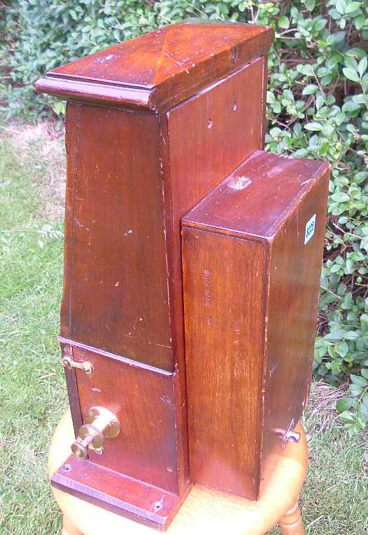
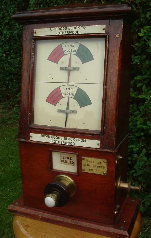 Note the plate saying 'OPEN AT LINE CLOSED ONLY' on the front - more about this later. The
instrument has been modified by the addition of a back box:
Note the plate saying 'OPEN AT LINE CLOSED ONLY' on the front - more about this later. The
instrument has been modified by the addition of a back box:
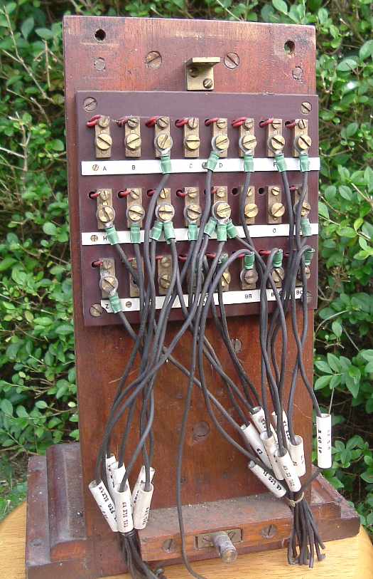
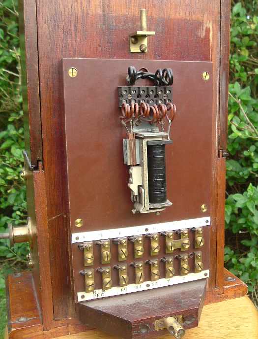
 Opening the back box, we find the BCS relay and a neat set of screw terminals. Note
that terminals E and F are provided, suggesting that whoever modified the instrument intended to
provide for track circuit control of the needle, although the terminals are presently shorted
together. Curiously, this instrument is not fitted with contacts C2 or terminals H-J, which are also associated
with track circuit control of the needle. Also, the top contacts of BCS have been shorted out (two wires in one hole in the
terminal block), so in its final form, this instrument had no block controls whatsoever!
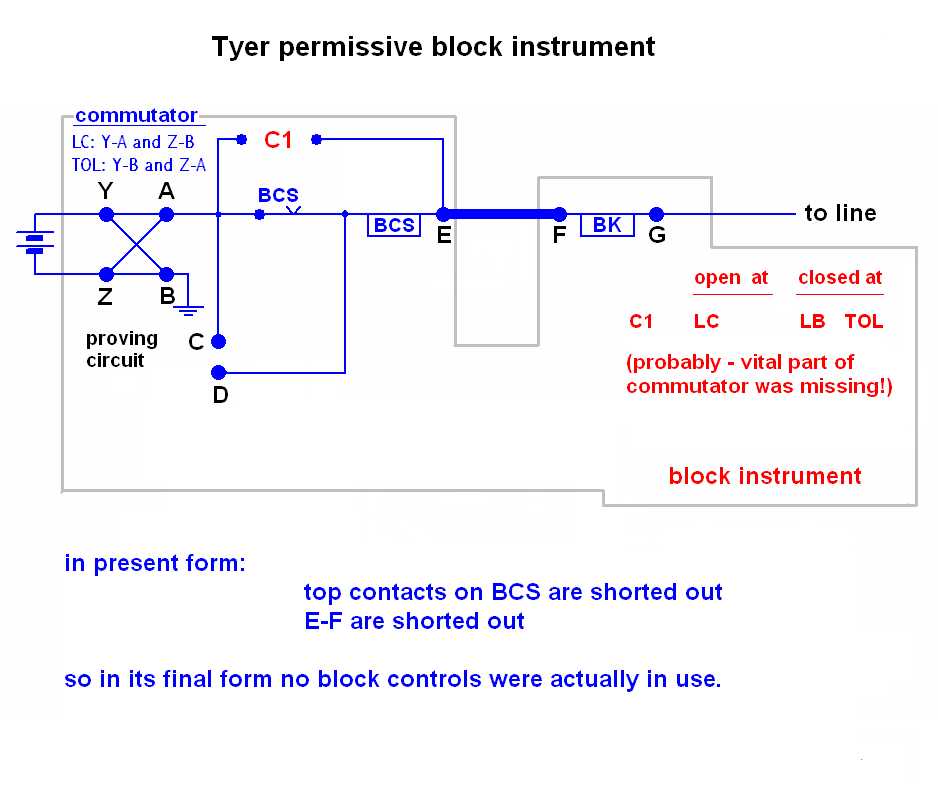
The circuit diagram for this instrument is shown here.
Opening the back box, we find the BCS relay and a neat set of screw terminals. Note
that terminals E and F are provided, suggesting that whoever modified the instrument intended to
provide for track circuit control of the needle, although the terminals are presently shorted
together. Curiously, this instrument is not fitted with contacts C2 or terminals H-J, which are also associated
with track circuit control of the needle. Also, the top contacts of BCS have been shorted out (two wires in one hole in the
terminal block), so in its final form, this instrument had no block controls whatsoever!
The circuit diagram for this instrument is shown here.
 Of course, the proving circuit requires a contact (C1) which is broken at line clear. Unlike
the drop handle blocks, the
commutator shaft cannot be extended to the rear of the instrument, because a plunger for
ringing the block bell is located in the centre of the commutator. Instead, contact C1 is to be found inside
the instrument and is revealed on opening the front door:
Of course, the proving circuit requires a contact (C1) which is broken at line clear. Unlike
the drop handle blocks, the
commutator shaft cannot be extended to the rear of the instrument, because a plunger for
ringing the block bell is located in the centre of the commutator. Instead, contact C1 is to be found inside
the instrument and is revealed on opening the front door:
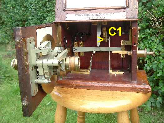 Unfortunately, this instrument was lacking a crucial part of the commutator when I obtained it,
and I have fitted a replacement.
Unlike my replacement, the original must have been 'non-standard',
with a suitable protrusion to force contact C1 open with the commutator
in the line clear position. Presumably this protrusion would also prevent the door from being
closed in the line clear position - hence the warning notice on the front!
I have documentary evidence (in the form of block shelf layout diagram)
that Sheffield No 3 had a Tyer permissive instrument fitted with
Welwyn control. This instrument worked the main lines to Sheffield No 2. I assume that
the reason for this is that Absolute Block working applied when No 2 switched out, and
No 3 worked through to No 1. It would be very interesting to see the wiring diagrams for this
instrument, or even the instrument itself, if it still exists!
Unfortunately, this instrument was lacking a crucial part of the commutator when I obtained it,
and I have fitted a replacement.
Unlike my replacement, the original must have been 'non-standard',
with a suitable protrusion to force contact C1 open with the commutator
in the line clear position. Presumably this protrusion would also prevent the door from being
closed in the line clear position - hence the warning notice on the front!
I have documentary evidence (in the form of block shelf layout diagram)
that Sheffield No 3 had a Tyer permissive instrument fitted with
Welwyn control. This instrument worked the main lines to Sheffield No 2. I assume that
the reason for this is that Absolute Block working applied when No 2 switched out, and
No 3 worked through to No 1. It would be very interesting to see the wiring diagrams for this
instrument, or even the instrument itself, if it still exists!