ex-GNR mechanical block
Towards the end of its existence, the GNR introduced a combined block instrument, pegging and non-pegging instruments, as well as the bell and tapper, being built into a single unit. The most remarkable feature was the lack of neeedle indicator for the pegging instrument - instead a mechanical pointer was attached to the commutator. In a sense this was a step back from instruments built decades before; use of needle indicators at both ends of the section - and wired in series with each other - provided an assurance that the same indication was displayed at both signal boxes.
The commutator was electrically the same as that on many other early block instruments. However, when block controls came to be applied, this had to be done differently to the other instruments. Perhaps the best known examples were those at Spalding No 1 which are illustrated on John Hinson's Signal Box site.Richard Pike has kindly sent me wiring diagrams for the instruments at Spalding No 1. The circuit is shown here:
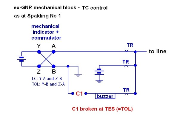 The instruments were used with a form of track circuit control. When the Track Circuit is
occupied, TR drops, connecting negative battery to line, thus forcing the needle at the
other end of the section to Train on Line. Also, the battery is connected to the buzzer,
which sounds until the commutator is moved to Train on Line, if not in that position
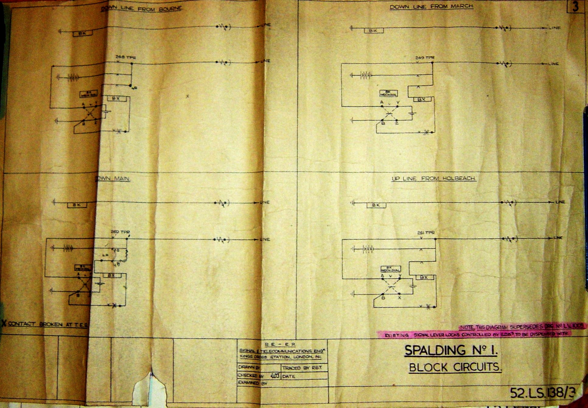
already. The original diagram is here
(799 kB).
At Spalding No 3, the same type of instrument was used for the section to Surfleet, with slightly
more sophisticated controls. Here is the circuit, again from a diagram supplied by Richard:
The instruments were used with a form of track circuit control. When the Track Circuit is
occupied, TR drops, connecting negative battery to line, thus forcing the needle at the
other end of the section to Train on Line. Also, the battery is connected to the buzzer,
which sounds until the commutator is moved to Train on Line, if not in that position
already. The original diagram is here
(799 kB).
At Spalding No 3, the same type of instrument was used for the section to Surfleet, with slightly
more sophisticated controls. Here is the circuit, again from a diagram supplied by Richard:
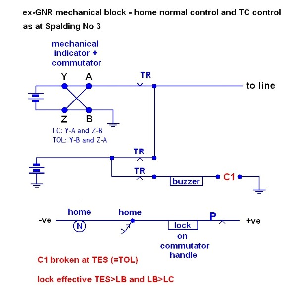 The track circuit and buzzer operate in the same way as at Spalding No 1. Home normal control
is provided by means of an electric lock on the commutator, which must be released
to allow movement from Train on Line to Line Blocked, and from Line Blocked to Line Clear.
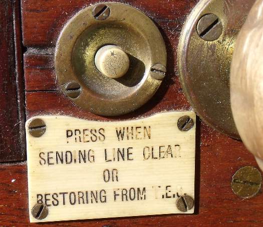
To release the lock, one presses a plunger on the front of the instrument, which completes
the lock circuit, provided the home signal is normal and its lamp is proved alight. The
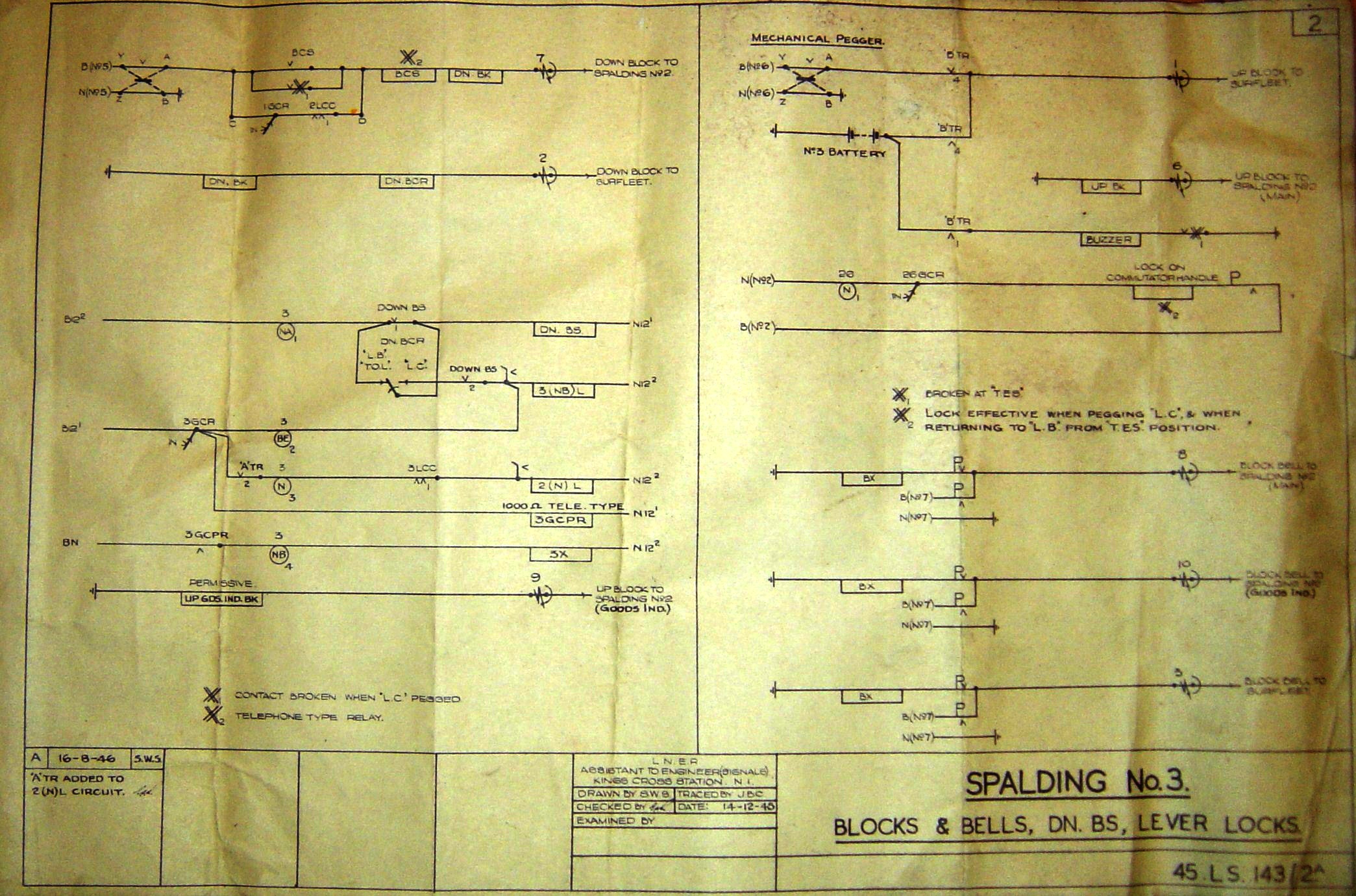
original diagram is here
(911 kB).
According to the Accident Report, instruments of this sort were in use on the main lines
at Welwyn Garden City at the time of the accident there in 1935.
Here is a modified instrument - of unknown origin - in real life:
The track circuit and buzzer operate in the same way as at Spalding No 1. Home normal control
is provided by means of an electric lock on the commutator, which must be released
to allow movement from Train on Line to Line Blocked, and from Line Blocked to Line Clear.
To release the lock, one presses a plunger on the front of the instrument, which completes
the lock circuit, provided the home signal is normal and its lamp is proved alight. The
original diagram is here
(911 kB).
According to the Accident Report, instruments of this sort were in use on the main lines
at Welwyn Garden City at the time of the accident there in 1935.
Here is a modified instrument - of unknown origin - in real life:
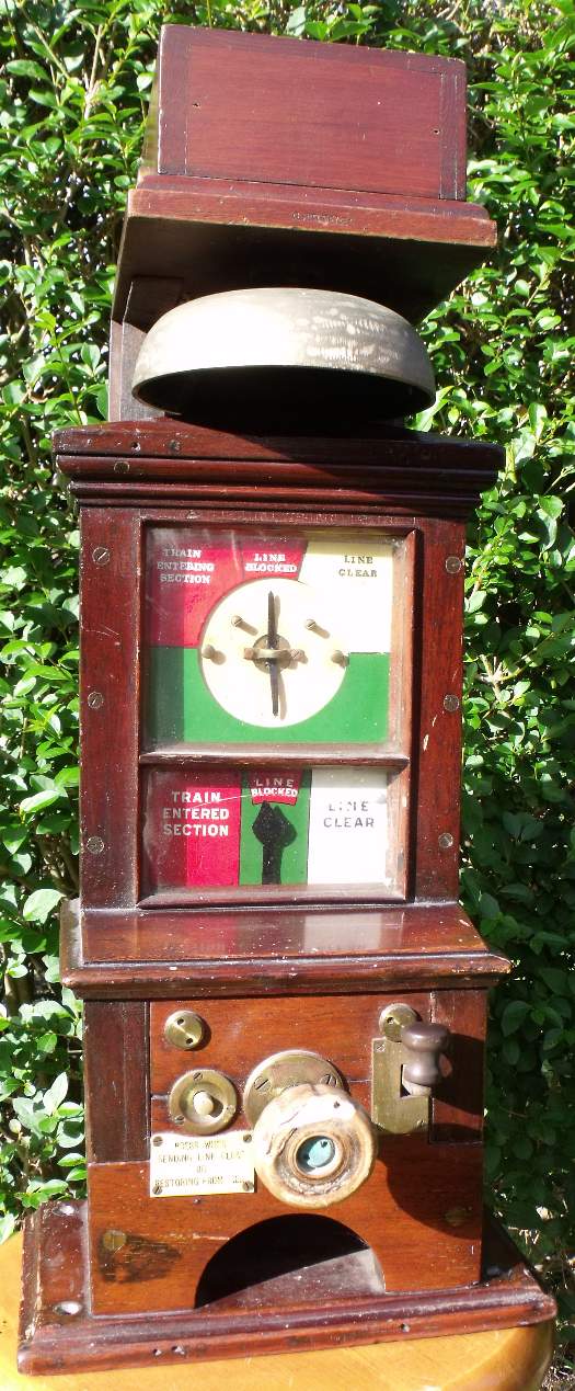 Notice the wording Train Entering Section and Train Entered Section instead
of Train on Line. This was typical Great Northern practice.
Here's a close up of the plunger:
Notice the wording Train Entering Section and Train Entered Section instead
of Train on Line. This was typical Great Northern practice.
Here's a close up of the plunger:
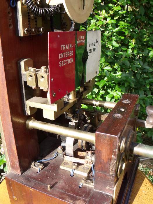
 Here is the interior showing the pegging part of the instrument. The black pointer is
extremely flimsy! Additionally, what appear to be electrical contacts are present behind
the dial, but these are not used and appear to be incomplete.
Here is the interior showing the pegging part of the instrument. The black pointer is
extremely flimsy! Additionally, what appear to be electrical contacts are present behind
the dial, but these are not used and appear to be incomplete.
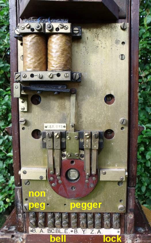
 Here is a rear view, with the back box cover removed. The electric lock is prominent.
The row of terminals at the bottom is rather similar to many modified other instruments.
Note also the contact disc attached to the commutator, with two sets of
contacts, one set marked TES CTS.
Here is a rear view, with the back box cover removed. The electric lock is prominent.
The row of terminals at the bottom is rather similar to many modified other instruments.
Note also the contact disc attached to the commutator, with two sets of
contacts, one set marked TES CTS.
 So far, so good, but at this point, things start to get puzzling. I dismantled the
rear contacts and contact disc:
So far, so good, but at this point, things start to get puzzling. I dismantled the
rear contacts and contact disc:
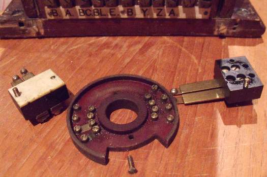 Why should there be four positions when the commutator only has three? Also,
the TES contacts are closed at Line Blocked; the Train on Line pair appear to be
burnt out... And what are the second set of contacts for? - none of them are used.
Need more investigations (and photographs!) here...
Why should there be four positions when the commutator only has three? Also,
the TES contacts are closed at Line Blocked; the Train on Line pair appear to be
burnt out... And what are the second set of contacts for? - none of them are used.
Need more investigations (and photographs!) here...