early circuits
It appears that the earliest control applied to 3 wire, 3-position block was that which requires the home signal to be on before line clear can be pegged - i.e. home normal control. This requires a single stick relay. There are two versions of the circuit.
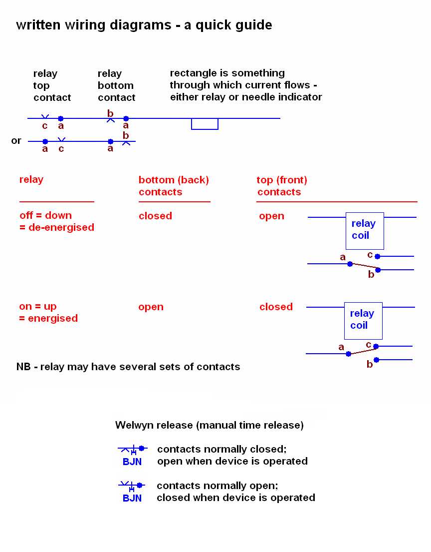
 (Puzzled by written wiring diagrams? try this quick guide)
The operation of the circuit is the same in either case. At Line Blocked, no current is sent to the
block line. At Train on Line, negative battery is sent to line.
Now suppose we want to peg line clear. BCS will be down (de-energised), and so the proving
circuit must be closed, i.e. home signal at danger (the proving
circuit may also check the distant signal, and that the relevant signal lamps are alight).
On moving the commutator to Line Clear, BCS picks up, closing its top contact. The home signal
can now be cleared, and BCS will stay up, fed through its own top contact. BCS drops when we move
the commutator to Line Blocked.
The two circuits differ only in whether BCS is by-passed by contact C1. This makes no difference as far as
home normal control is concerned. It became significant later on, when this circuit was used as a component
of more sophisticated controls - see Circuits 1A and 1B. Eventually form B was preferred.
The later circuits had a characteristic style of construction (lettered screw terminals, way contacts
were added to block instrument, etc),
so I have assigned to 'early circuits'
any example of home normal control which appears to be different!
Example 1
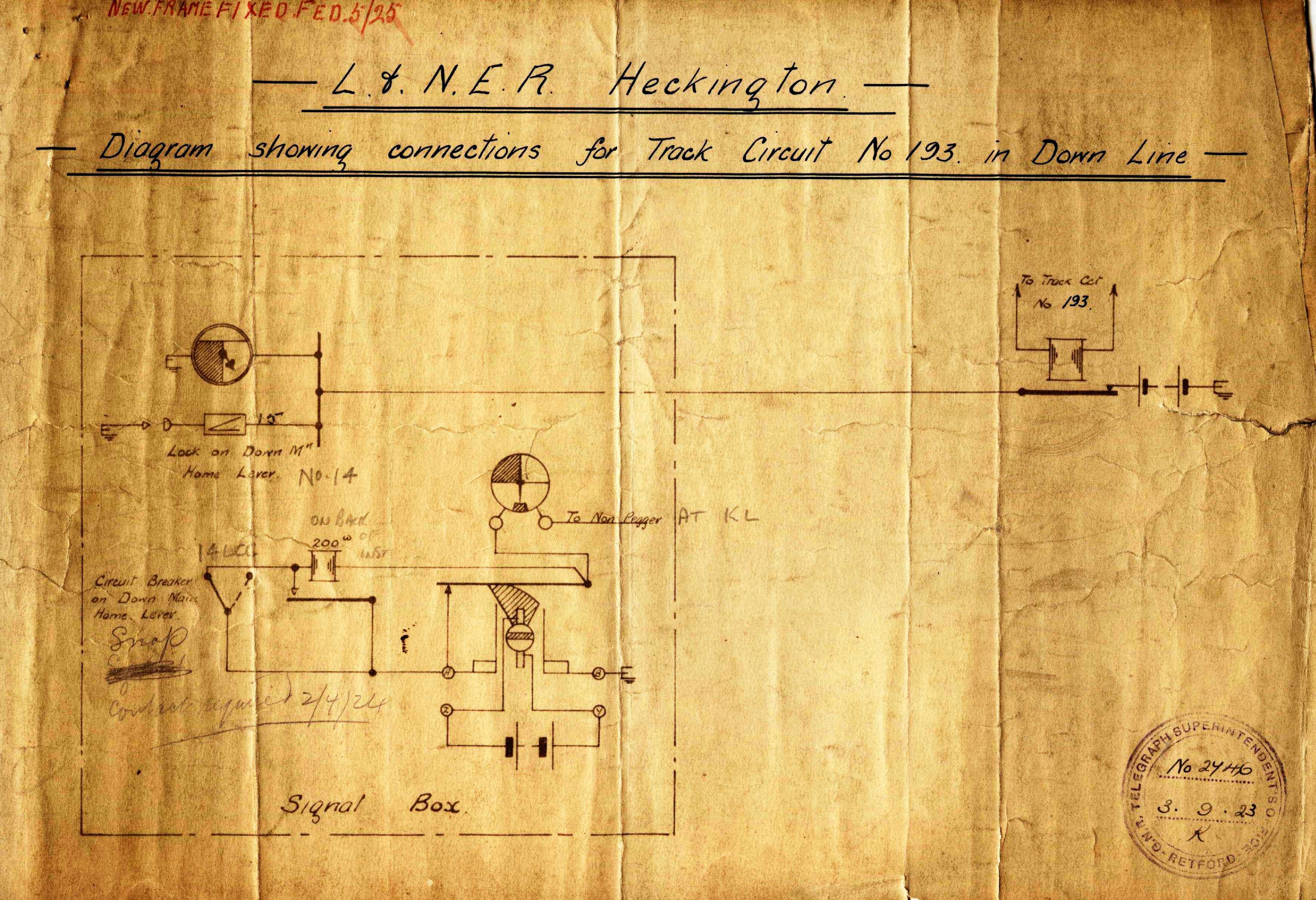
Richard Pike sent me this nice early drawing
showing home normal control applied to the down main block at Heckington (large file - 941 kb).
The diagram also shows the down main home lever locked by a track circuit.
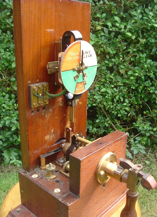
Example 2
This GCR instrument has seen better days - the needle is broken, for a start! - but is still
interesting. It is reputedly from the Leicester area, and is shown below with
the cover removed:
(Puzzled by written wiring diagrams? try this quick guide)
The operation of the circuit is the same in either case. At Line Blocked, no current is sent to the
block line. At Train on Line, negative battery is sent to line.
Now suppose we want to peg line clear. BCS will be down (de-energised), and so the proving
circuit must be closed, i.e. home signal at danger (the proving
circuit may also check the distant signal, and that the relevant signal lamps are alight).
On moving the commutator to Line Clear, BCS picks up, closing its top contact. The home signal
can now be cleared, and BCS will stay up, fed through its own top contact. BCS drops when we move
the commutator to Line Blocked.
The two circuits differ only in whether BCS is by-passed by contact C1. This makes no difference as far as
home normal control is concerned. It became significant later on, when this circuit was used as a component
of more sophisticated controls - see Circuits 1A and 1B. Eventually form B was preferred.
The later circuits had a characteristic style of construction (lettered screw terminals, way contacts
were added to block instrument, etc),
so I have assigned to 'early circuits'
any example of home normal control which appears to be different!
Example 1
Richard Pike sent me this nice early drawing
showing home normal control applied to the down main block at Heckington (large file - 941 kb).
The diagram also shows the down main home lever locked by a track circuit.
Example 2
This GCR instrument has seen better days - the needle is broken, for a start! - but is still
interesting. It is reputedly from the Leicester area, and is shown below with
the cover removed:
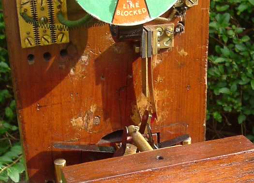
 Contact C1, which opens
when the commutator is moved to line clear, is of a different form to that found on instruments
with the later, standard, circuits. The contact is shown below in the open position:
Contact C1, which opens
when the commutator is moved to line clear, is of a different form to that found on instruments
with the later, standard, circuits. The contact is shown below in the open position:
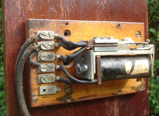
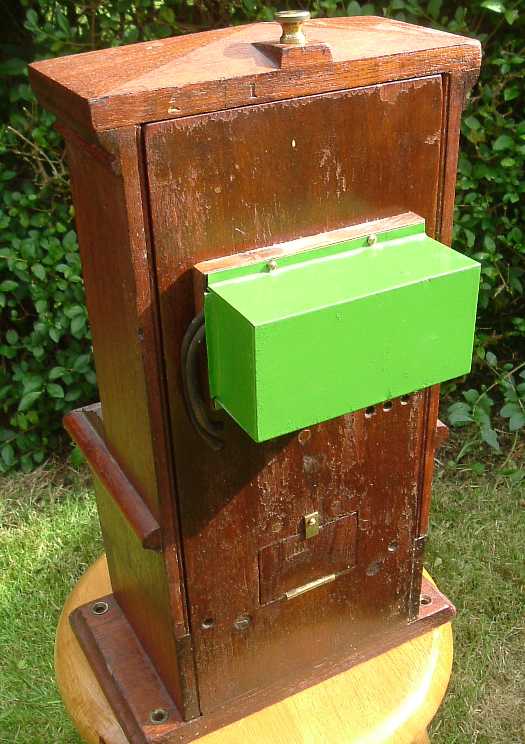
 On the back of the instrument, we find a small metal box. Most back boxes on LNER instruments
were made of wood. The bright green paint was added recently.
On the back of the instrument, we find a small metal box. Most back boxes on LNER instruments
were made of wood. The bright green paint was added recently.
 Open the back box, and we find a single relay. Enough wires remain to show that this is an
example of home normal control, version A.
Open the back box, and we find a single relay. Enough wires remain to show that this is an
example of home normal control, version A.