|
home
railway pages
block instrument wiring
LNER instruments
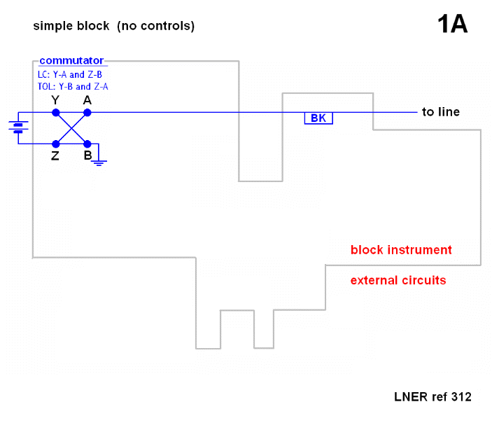
simple block
early circuits
ex-GNR mechanical
block
circuit 1A theory
circuit 1B theory
circuit 2 theory
circuit 1A examples
circuit 1B examples
circuit 2 examples
circuit 1+2 hybrid
Welwyn release
some questions
|
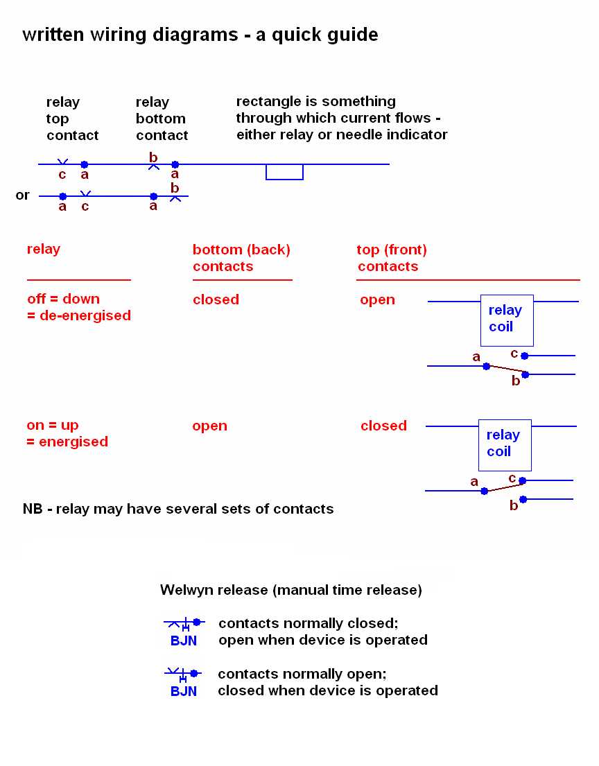
(Puzzled by these wiring diagrams? Yes, I was too when I first met them, but then
my background is a degree in physics, not a career in the S+T! Actually, they are
quite simple - try this quick guide)
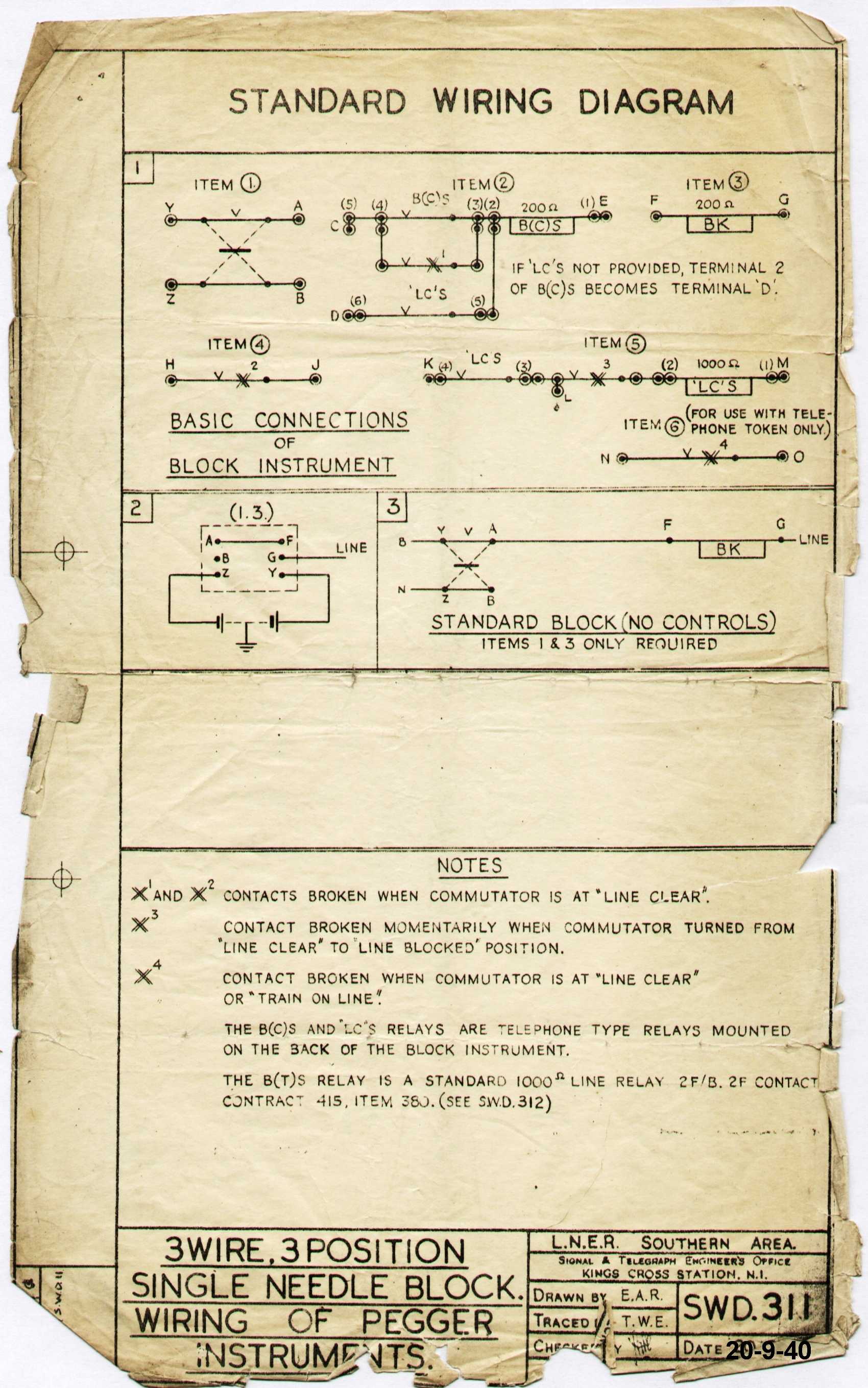
LNER references
SWD 11, dated 20 September 1940. This was renamed to
SWD 311 on 21 September 1950, without any other
changes. and
SWD 12, dated 25 September 1940. This was renamed to
SWD 312 on 21 September 1950, without any other
changes.
These notes assume line clear = positive to line, following the Standard Wiring Diagrams.
This was usually the case on the LNER - but there were exceptions.
key features:
allows signal proving, track circuit control and Welwyn control to be added
incrementally
full circuit requires three stick relays:
BCS = proving circuit stick relay (sometimes called home normal control)
BTS = track circuit repeating stick relay (sometimes referred to as TPS)
LCS = line clear stick relay (Welwyn control)
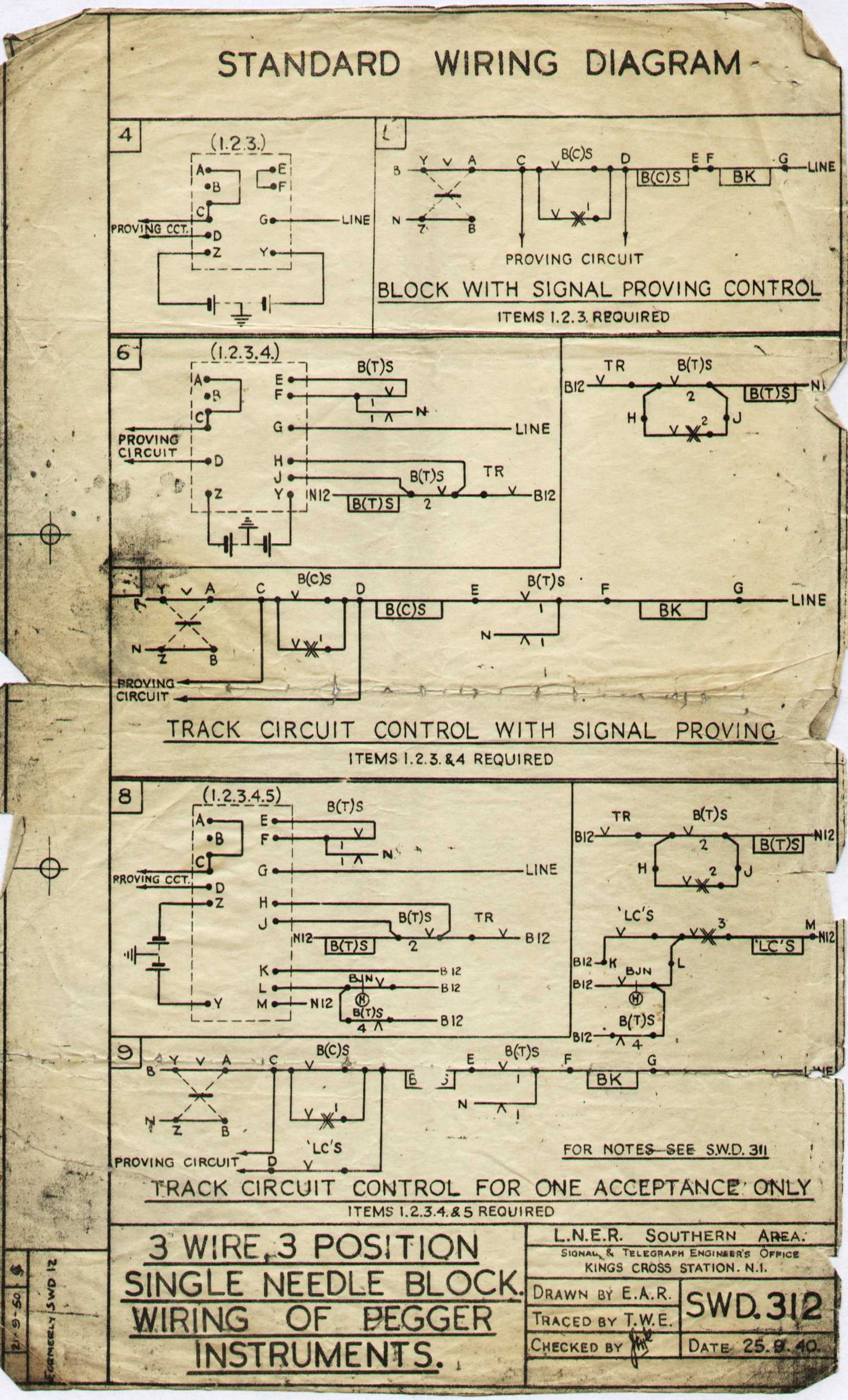
circuit operation
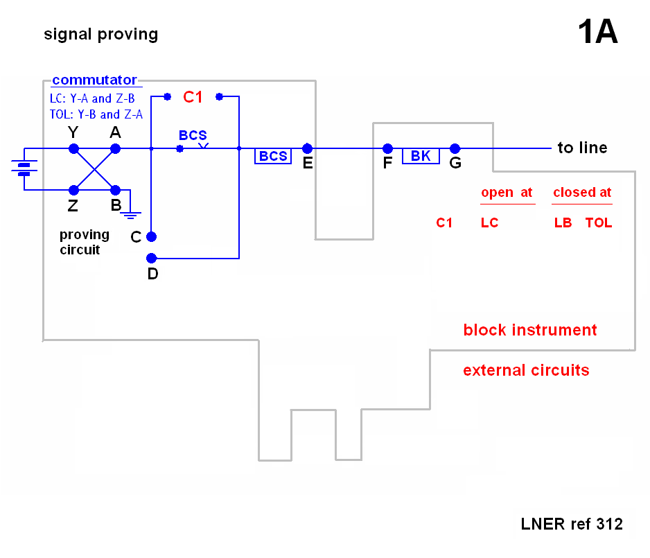
signal proving only (click for single diagram)
We start with BCS down (=de-energised) and the commutator at line blocked. Suppose we move
the commutator to line clear. C1 contacts are open, so no current can be sent to line unless
contacts C-D are closed. The proving circuit closes C-D when certain conditions are met:
as a minimum, the home signal must be at danger, but often requires also that the distant signal
is at caution and both
home and distant lamps are lit.
With C-D closed, current flows to line and BCS picks (or rather sticks) up. The proving circuit
can now be broken (e.g. signals pulled off)
but BCS will stay up - since it is fed through its own top contacts - as long as the commutator is at line clear.
With the commutator at train on line, C1 contacts are closed, so train on line can be
sent out, regardless of the state of BCS.
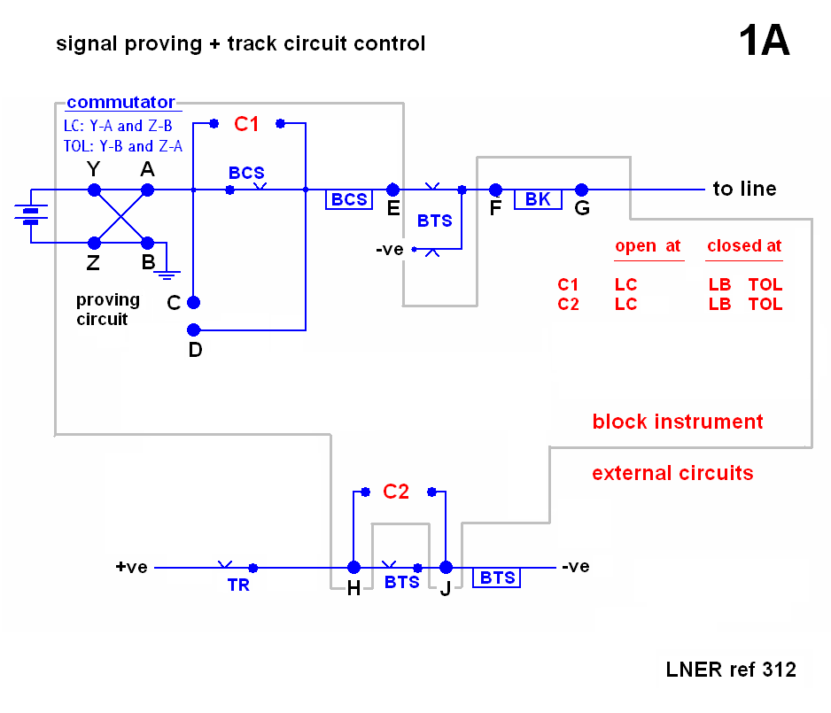
signal proving and track circuit control (click for single diagram)
This requires a track circuit in rear of the home signal. The circuit is arranged to force the block
indication to train on line, whenever the track circuit is occupied, regardless of the position of the commutator.
To do this, a relay - BTS - is inserted between the commutator/signal proving circuit and the block needle.
With BTS up, whatever we peg on the commutator is connected to the needle and sent to line
(signal proving circuit permitting).
BTS is wired in series with its own top contacts (so it is a stick relay) and also the track circuit
relay (TR). Therefore it drops whenever the track circuit is occupied.
Negative battery is then connected to the needle, and train on line sent - even if the commutator is not at
train on line.
The train proceeds on its way and the track circuit clears. BTS stays down - and the needle at train on line -
until contacts C2 are closed; this occurs when the commutator is moved from the line clear position. In other words,
if we had left the commutator at line clear, the needle stays at train on line until we move the commutator to
line blocked.
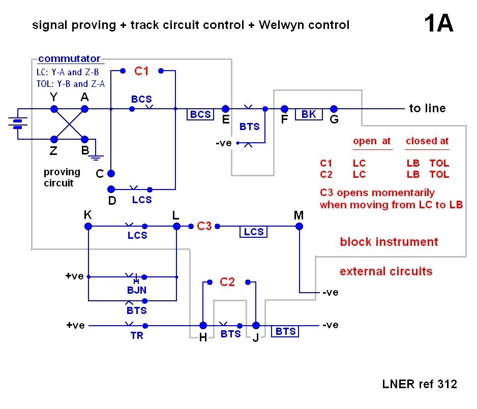
signal proving, track circuit and Welwyn control (click for single diagram)
This includes the features of the previous two circuits, with an important addition: once we have pegged line
clear, we cannot send out another line clear, until the home berth track circuit has been occupied and cleared.
This is commonly called Welwyn control. The circuit to do this requires one more stick relay - LCS - and can be thought of
as a sort of enhanced proving circuit.
Let's consider the operation starting with LCS up, which is required to peg line clear (notice the top contacts of
LCS adjacent to terminal D). So provided LCS is up, and C-D (proving circuit) closed, we can peg line clear.
In due course we get 'train entering section' and move the commutator to train on line. In moving the commutator away from
line clear, C3 opens briefly, and this drops LCS. (The breaking of contacts C3 is is accomplished with ratchet like arrangement
in the block instrument, which will be illustrated later). If we were to now try and peg another line clear, we would not
succeed, since LCS is down.
There are two ways to re-energise LCS. The usual one is to drop BTS, i.e. occupy the track circuit. It is also possible
by operating BJN, which is the Welwyn release device with the winding handle. With this particular circuit, operation
of BJN simply re-energises LCS and does not place the block needle to train on line.
In its original form, this circuit contains a surprising flaw. Consider what happens if we wind the release device just
until LCS picks up (either the relay clicks or the needle goes to Line Clear -
not difficult to do in practice), and then leave it in that position. LCS will now remain up permanently, so that the whole
purpose of Welwyn control has been defeated, yet we can carry on signalling trains!
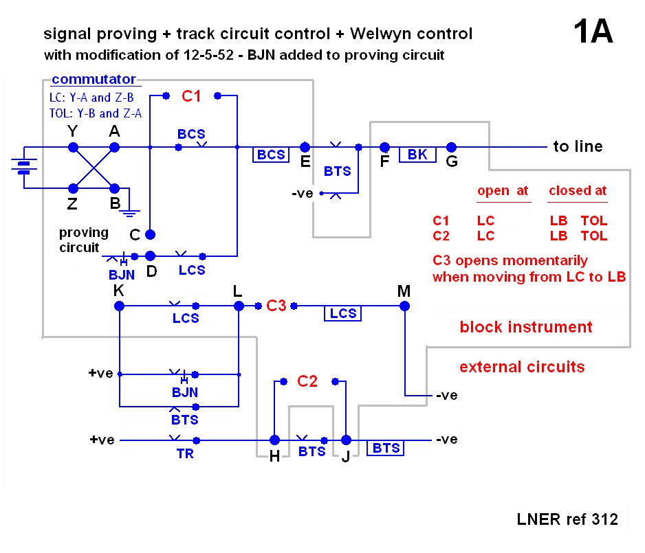
A note dated 12-5-52 indicates the circuit was modified to remove this flaw, by putting a normally closed set
of release contacts in series with the proving circuit -
here is the circuit. Operation of the Welwyn release now breaks the proving circuit, preventing line clear from
being sent to line, until the release has been wound back fully to its original position.
(To see the note on the LNER diagram, refer to SWD 312B and Circuit 1B).
|
|