|
|
|
|
| home railway pages block instrument wiring LNER instruments simple block early circuits ex-GNR mechanical block circuit 1A theory circuit 1B theory circuit 2 theory circuit 1A examples circuit 1B examples circuit 2 examples circuit 1+2 hybrid Welwyn release some questions |
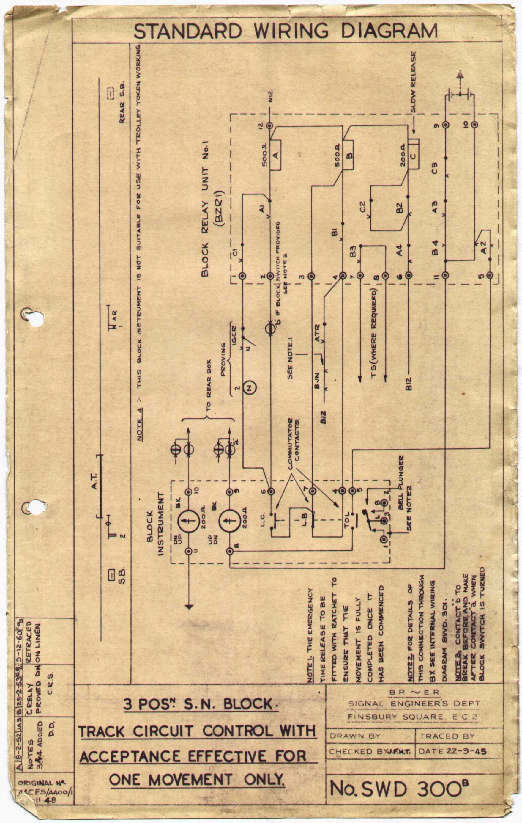
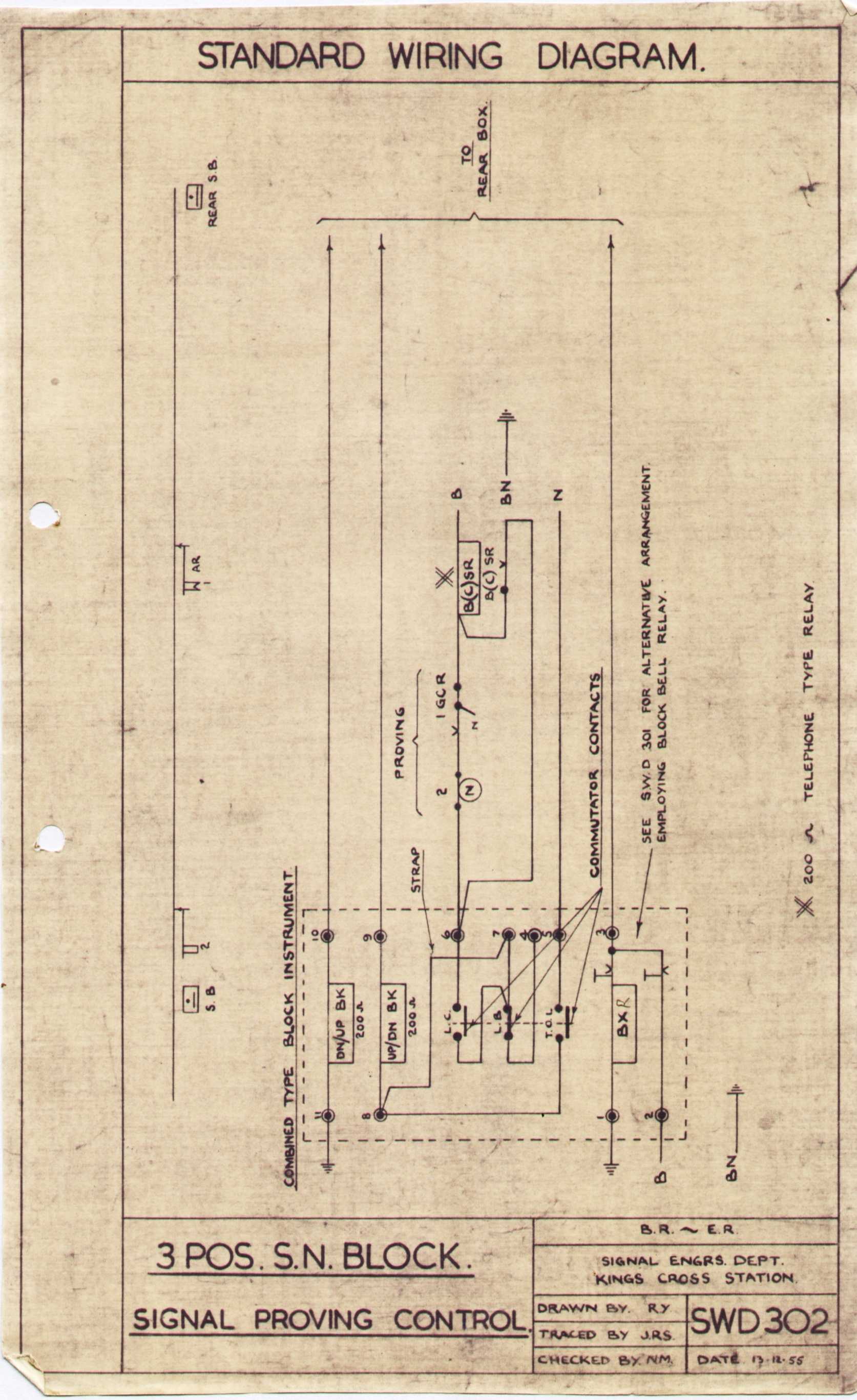
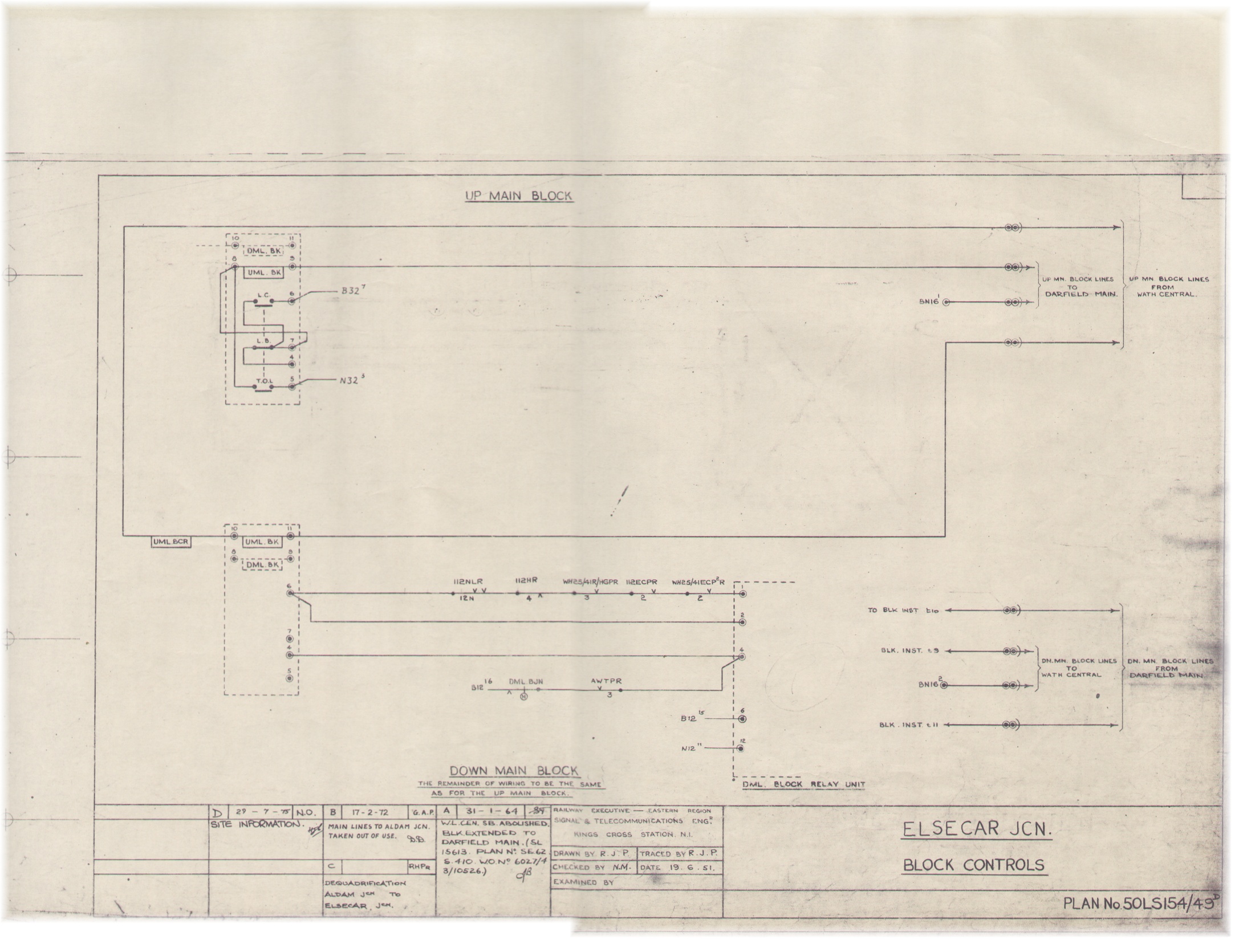
Block controls using Circuit 2 are found in association with the Tyer 'Black Box' instruments. The NER/LNER double line block instruments are electrically identical - apart from the lack of block bell - and I assume (though cannot prove) they were used in the same way. LNER / BR(ER) references: SWD 301A internal wiring of Tyer 'Black Box' instrument, 22 September 1945. SWD 300B circuits for full block controls using BZR1 unit: signal proving, track circuit control, and Welwyn control, 22 September 1945 This type of instrument could also be used with signal proving alone: SWD 302 signal proving only, 13 December 1955 Sometimes it was wired without any controls (free block), as in this example at Elsecar Junction, which controlled the up main from Darfield Main. (809 kb). To collectors of block instruments, instruments using Circuit 2 are perhaps less interesting than those using Circuits 1A and 1B, since most of the circuitry is contained in an external relay unit called 'BZR1', rather than the block instrument itself. I have never actually met one of these in real life, although I have built the circuit with modern relays. With the BZR1 unit, the power supply, which is connected to the block line, is isolated from the block control relay circuits. This offers some advantages: if a high voltage is required for the block line, perhaps owing to intermediate signal boxes being switched out, we will not risk damaging the block control relays. In contrast, with circuit 1, the signal proving stick relay was wired in series with the block line. The bell may also be isolated from block line via a relay; again, this can be advantageous. If only a weak pulse is received due to intermediate signal boxes being switched out, provided the relay picks, the bell will still ring at the same volume. Brief Description of Circuit Operation with BZR1 unit (full block controls) The circuit is built around three stick relays: A (for signal proving), B (for track circuit control) and C (for Welwyn control). At Line Blocked, the usual state is A down, B up and C up. Now let's turn the commutator to Line Clear. Current (positive battery), flows through BJN (if release switch in correct position), through the track repeating relay ATR (if up, i.e. track circuit clear), through B1 top contacts, through block instrument terminal 7, to block instrument terminal 6, and then - provided the proving circuit is closed and C is up - finally through relay A. A then sticks up. C then drops (slowly, to allow time for A to pick up). With A up, B up and finally C down, positive battery is connected to line - via terminals 9 and 10 of BZR1 unit and block instrument terminals 8 and 9. When we move the commutator to Train on Line, A drops, connecting neagative battery to line, via BZR1 unit terminals 10 and 5 and the (now closed) Train on Line contacts of the commutator. If the train reaches the track circuit before this, ATR and then B drop. B down also connects negative battery to line (BZR1 terminals 10 and 11). A down and B down (track circuit occupied) will cause C to stick up again. When the train clears the track circuit, B will pick up again as soon as the commutator is moved to Line Blocked. In this circuit, the Welwyn time release device mimics the action of the track circuit, by causing B to drop.
|
|