how it works
The present simulator is based around a number of PIC (say 'pick') microcontroller chips. It has been developed in my spare time over the last 5 years - with by far the greatest part of the effort going into developing the software.
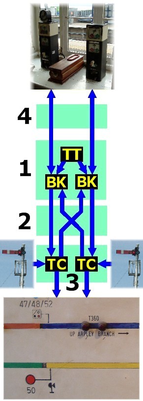
The simulator is built in a modular fashion, using four types of circuit board. Construction of these is described in more detail on the construction pages. My original simulations were of simple 'straight up and down' working, but it is now possible to combine the modules to reproduce more complex layouts, having more than two adjacent block posts. To understand how it works, it is easiest to start by considering a simple, plain double track, block post: Circuit Board #1 - Block Post module This contains one 'timetable' ( TT ) and two 'block post' ( BK ) chips. The 'timetable' (or 'master control') chip holds the information describing the trains to be signalled. This information - basically an extract from the train register book - is typed into a text file, which is used to automatically generate the PIC assembler file. At the appropriate time, a train is 'triggered' by sending appropriate information to one of the block post chips. The block post chips are identical and simulate the adjacent signal boxes. They look after the bell ringing and non-pegging block indicators. They can either offer trains to us (after being triggered by the timetable chip), or we can offer trains to them. It is possible for us to refuse a train initially, and accept it later by repeating the 'is line clear' code. The block post chips can distinguish specific bell codes, and so - for example - it is possible for us to block back (3-3 or 2-4). After a train has been accepted by us, there follow the bell signals for train approaching (optional), train entering section, and then when the train reaches our track circuits, an electrical signal is sent to one of the track circuit chips. Circuit Board #2 - Block / Track Circuit interface This board simply passes the electrical signal representing a train originating at A to, say, the up line track circuit chip. Trains leaving the up line track circuit chip are passed on to box C (for an A-B-C configuration, we are box B). Conversely, trains originating at box C are passed on to the down line track circuit chip, and on leaving this chip, on to box A. Circuit Board #3 - Track Circuit Module This module contains two 'track circuit' chips ( TC ). Each of these reads the state of the signals, and looks after the illumination of the track circuit lamps. For each line, there are seven inputs (usually signals - one signal per route) and nine outputs (usually to the track circuit lamps). You will see why I say 'usually' later on. The track layout is specified in a text file, which is again used to automatically generate the PIC assembler code. For a simple up/down simulation, you would have two files. This information includes track circuit lengths, train lengths and TC/signal assignments on the PIC. The layout itself is specified in a 'track circuit A, via signal 1, leads to track circuit B; track circuit A, via signal 2, leads to track circuit C' sort of fashion. Train lengths are currently coded by the timetable chip as 'light engine', short, medium or long etc, and actual lengths (in yards) are specified in the track layout file. Circuit Board #4 - Block shelf interface At present this board doesn't do much, and effectively only links a 10 way IDC connector to a 9 way D type connector. Nevertheless, I put a board here as this is the most convenient place to add block controls, and I may do this in the future. How to do a more complex layout The system so far described would enable us to have two adjacent (to us!) block posts, and on each line there could be up to nine track circuits and seven signalled routes. This might allow us, for example, to have up and down loops (Ashby Magna springs to mind as a suitable example - except that it was not Absolute Block on all lines!). But trains from A always go to C, and trains from C always go to A. What if - for example - we want to cross a train from the up to the down line? A simple way of doing this is to use one of the inputs not as a conventional signal, but as a message to the down line PIC to 'start train on specified track circuit'. To the up line PIC, the train just vanishes. This does require that the train which 'appears' on the down line PIC has preset properties (train length and time in advance section), and also a train cannot stop 'straddling' the up/down crossover (since the up chip will proceed to extinguish its TC lamps regardless of what is happening on the down line!). But these limitations are not too serious, and still allow plenty of interesting layouts. In just the same way, it is possible to connect more modules together to simulate a junction.