North Lincolnshire
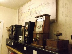
I hesitate to call this a simulation of Wrawby Junction, as readers will then expect a 137 lever frame! My aim was far more modest - to build something which would evoke trains crossing the North Lincolnshire Wolds using block instruments and bells. This is done - I think successfully! - by using four simulator modules to create a 4-track main line with interconnections. This can approximately recreate Wrawby, if we make some simplifications/deletions: the Brigg line is ignored; the sidings are ignored; and the Down Goods line is ignored. Nevertheless, that still captures most (probably >90%) of the through traffic. Therefore the lines included are up and down Yorkshire, up and down Lincoln, up and down fast to Barnetby East, up and down slow to Barnetby East.
You can think of this as a work in progress - I am still making modifications to it. Adding a fifth block module (for the Down Goods) would be possible in theory, but is not very convenient electrically, and also I've no extra room, so it is not likely to happen. The diagram is a copy of the original GCR Wrawby Junction diagram - which had to be slightly reduced in size (the original is stored away carefully!). The original has only six track circuits (for the home and starting signals at the west end of the layout, to Doncaster, Retford and Lincoln). I've added red lamps to these, and also added lamps corresponding to some of the modern TCs - just (barely) enough to make the simulation workable. The signalling has been simplified to just 8 routes over the junction; the starting signals to Elsham and Holton-le-Moor are ignored at the moment. In the simulation these 8 routes were originally controlled from a what was in effect a simple OCS panel (the simulator modules have one input (=switch) per route). In this case, the routes were interlocked with each other, but not with TCs. The simulations I've built were intended to bring to life the block instruments and diagram, and don't generally have any interlocking (the 8 routes here are an exception). However, the system will - as far as possible - detect errors by the user: bell ringing errors, pegging line clear with the home signal off or irregularly sending a train into section. A score is kept of the number of errors. As regards block instruments, the simulation really ought to have four 'Tyer's black box' instruments - or possibly a BR standard block for the fast lines (as was the case at the end). For the time being, the slow lines are worked by a GCR Tyer's permissive - partly as I had one wired up and sitting on the shelf already, but mainly because I just like these instruments! The system is presently programmed using information obtained from www.realtimetrains.co.uk for 22 Dec 2015 (but with down goods traffic sent over the down slow). Entry points (i.e. for offering the trains) are assumed to be Wickenby, Appleby and Brocklesby. As far as I know this is correct - and is the basis for my saying the setup evokes trains crossing the Lincolnshire Wolds. As far as I understand, in reality routing of trains was obtained from TRUST, or freights were described by circuit call when approaching Ulceby. The down fast and slow modules here have been modified to provide routing information 3 minutes before the train is offered - albeit in a very simple way: a white LED (for the White Rose county) or a yellow LED (for Yellow Belly county). Finally - for now! - the simple OCS panel described earlier was useable, but effectively ignored a critical and interesting feature of the layout. In the down direction, the junction points were within the clearing points. Thus the junction had to be set appropriately before line clear could be given. This feature, of course, cannot be replicated on a route setting system. Possibly I ought to use an IFS type interface, with switches corresponding to the appropriate levers. For now, though, I've opted for a simpler 'solution' to this 'problem' using a method which I think is logical enough, but never existed anywhere in reality. It works like this: The OCS panel was retained, but merely illuminates a white route light when the route has been set (which would be equivalent to points set and locked in reality), but does not clear the signal. Having got the white light (which in the down direction is equivalent to clearing point available - I think) you give line clear, with the signal still on. A separate switch clears the signal later on. The system will award penalty points if line clear is given with the signal off, or with no clearing point...
