circuit 1B
Circuit 1A was modified slightly over the years, and developed into Circuit 1B. Here are the full circuits for comparison. The differences relate to the way in which LCS is dropped.
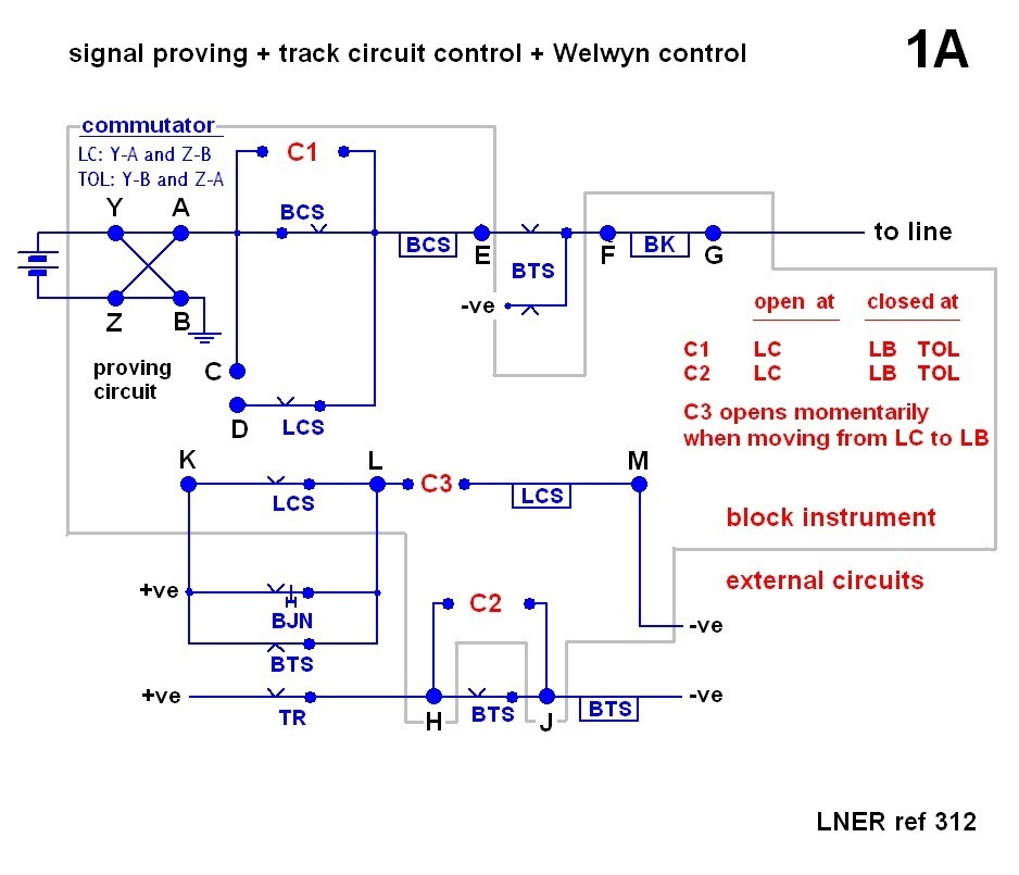
 circuit 1A (click for single diagram)
circuit 1B (click for single diagram)
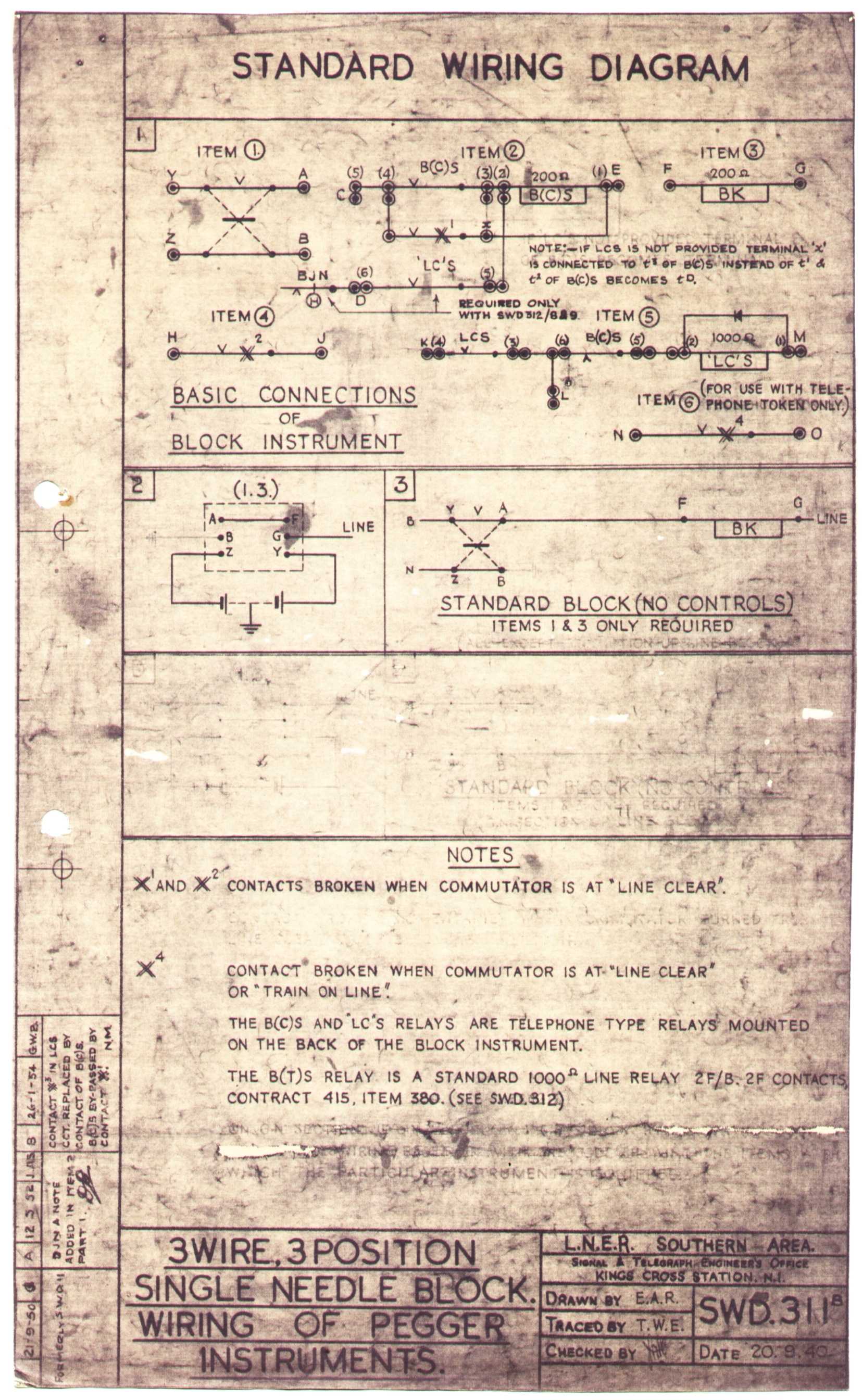
LNER references for circuit 1B: SWD 311B and
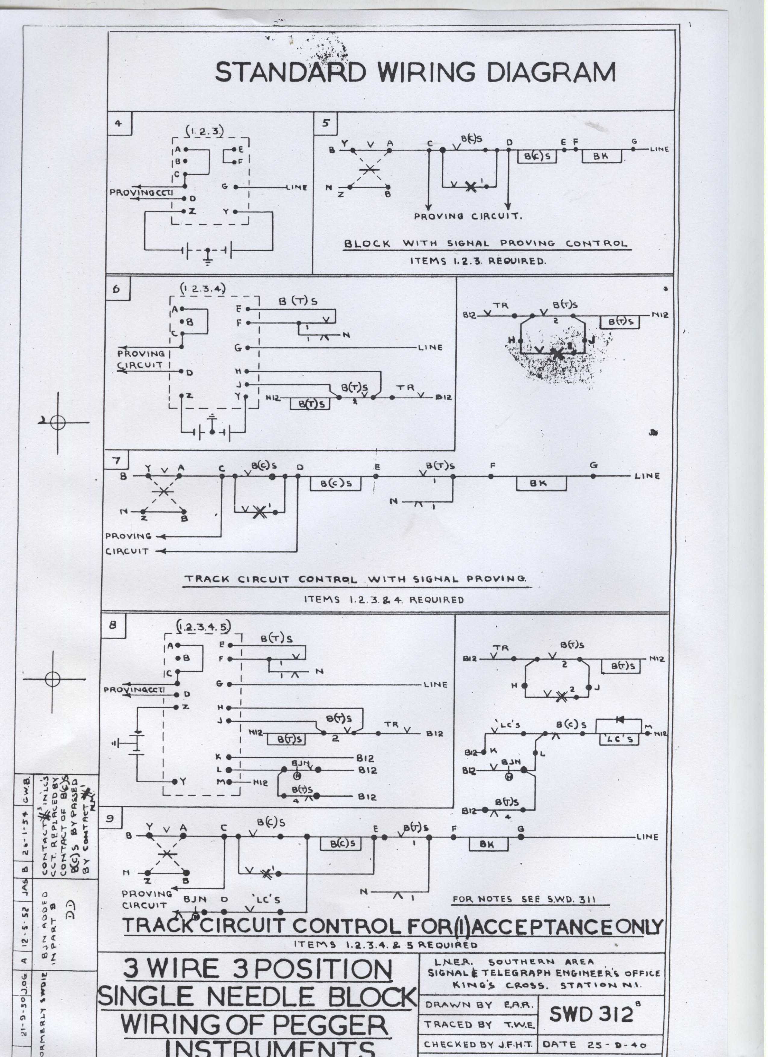
SWD 312B.
These were originally SWD 11 and SWD 12, respectively,
drawn in September 1940 (circuit 1A).
They were renamed to SWD 311 and SWD312 on 21 September 1950. Two amendements were
made to each diagram: 12 May 1952 (note regarding BJN - see notes on
circuit 1A for a discussion of this) and 26 January 1954 (contact #3 replaced
by BCS bottom contact, BCS by-passed by contact #1 - this is my circuit 1B).
differences
in circuit 1B:
There is no ratchet operated contact C3 to drop LCS. LCS is now fed through a bottom
contact of BCS, so when BCS picks up (on sending out line clear) LCS drops. Actually, LCS
must not drop immediately so that BCS has time to pick up - this is accomplished by
means of the rectifier, the back EMF across LCS holding it up for a fraction of a second.
(When operating one of these circuits, there is a brief, but perceptible, delay between
the needle moving to line clear and the click of LCS dropping).
The other difference is a consequence of the new method of dropping LCS:
Contacts C1 bypass BCS as well as a pair of its top contacts (note dated 26/1/1954). This
makes no difference if we omit Welwyn control and just use the proving circuit or track
circuit control. For Welwyn control, it is necessary: the Welwyn relay LCS is usually re-energised
when the block is at train on line and the track circuit occupied (BTS down). BCS must therefore
be down at this time (remember BCS up drops LCS), and this is not the case with circuit
1A. In circuit 1A, with the commutator at train on line, current flows through BCS - which
is not what we now want.
circuit 1A (click for single diagram)
circuit 1B (click for single diagram)
LNER references for circuit 1B: SWD 311B and
SWD 312B.
These were originally SWD 11 and SWD 12, respectively,
drawn in September 1940 (circuit 1A).
They were renamed to SWD 311 and SWD312 on 21 September 1950. Two amendements were
made to each diagram: 12 May 1952 (note regarding BJN - see notes on
circuit 1A for a discussion of this) and 26 January 1954 (contact #3 replaced
by BCS bottom contact, BCS by-passed by contact #1 - this is my circuit 1B).
differences
in circuit 1B:
There is no ratchet operated contact C3 to drop LCS. LCS is now fed through a bottom
contact of BCS, so when BCS picks up (on sending out line clear) LCS drops. Actually, LCS
must not drop immediately so that BCS has time to pick up - this is accomplished by
means of the rectifier, the back EMF across LCS holding it up for a fraction of a second.
(When operating one of these circuits, there is a brief, but perceptible, delay between
the needle moving to line clear and the click of LCS dropping).
The other difference is a consequence of the new method of dropping LCS:
Contacts C1 bypass BCS as well as a pair of its top contacts (note dated 26/1/1954). This
makes no difference if we omit Welwyn control and just use the proving circuit or track
circuit control. For Welwyn control, it is necessary: the Welwyn relay LCS is usually re-energised
when the block is at train on line and the track circuit occupied (BTS down). BCS must therefore
be down at this time (remember BCS up drops LCS), and this is not the case with circuit
1A. In circuit 1A, with the commutator at train on line, current flows through BCS - which
is not what we now want.